
Finally, a Replacement for the Relay Boards We Can't Buy Anymore
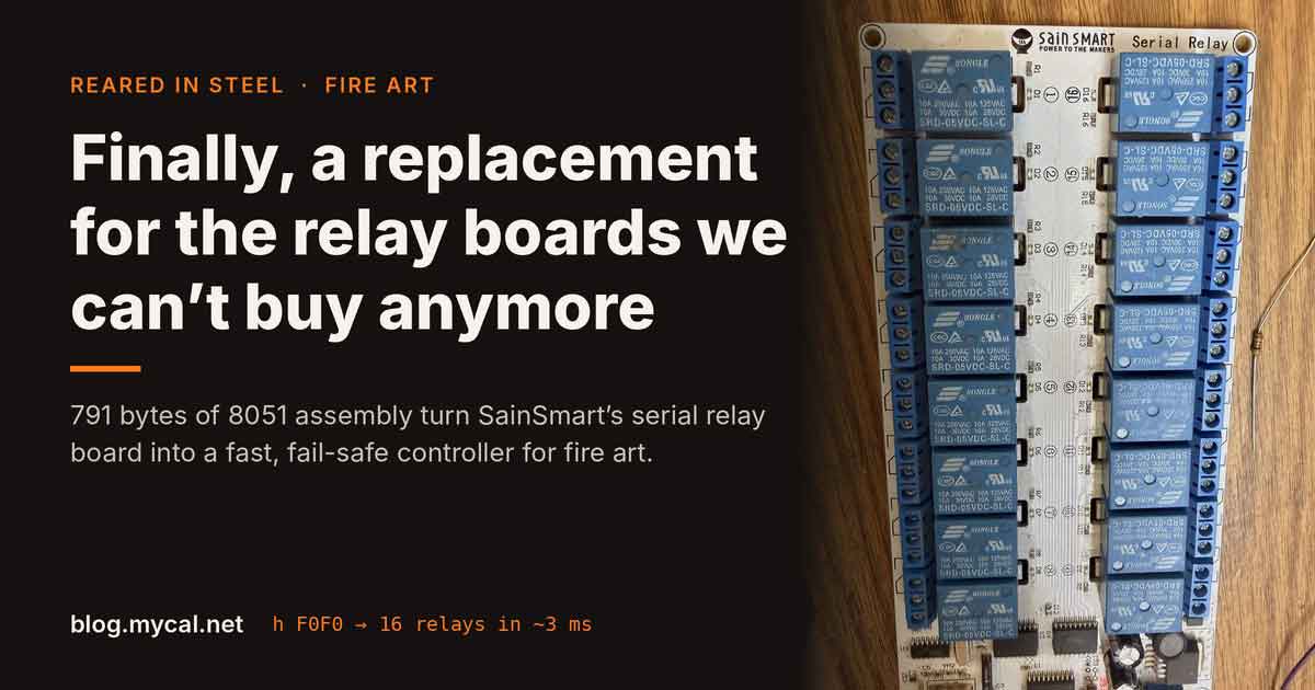
The SainSmart HID relay boards that run Reared In Steel’s fire art are gone, and their serial replacement takes 40 ms per relay. So I reflashed it: 791 bytes of 8051 assembly, all 16 relays in about 3 ms, on par with the old boards. Stored board IDs and failsafes make sure the right poofer fires.
Tinkering with Time, Tech, and Culture #66
Reflashing a SainSmart serial relay board with 791 bytes of 8051 assembly so our fire art can keep up with a MIDI keyboard again.
Picture playing a chord on an 88-key MIDI keyboard and watching sixteen propane effects go off one after another instead of all at once. That’s what the replacement for our old relay boards would have done out of the box. The fix turned out to be 791 bytes of hand-written 8051 assembly.
For years the fire effects on the Reared In Steel crew's pieces have run on SainSmart's USB-HID 16-channel relay boards. Propane poofers, the bigger propane effects and the igniters each sit behind a relay, the boards stack up, and a little C program I wrote back in 2017, usb-relay, gangs them into one long bitmask. We play them live from an 88-key MIDI keyboard, a MIDI controller and a web interface. Fire Kethedral runs seven boards. Medusa and Flower Tower run three or four each.
Those boards have hundreds of thousands of clicks on them now, and you can't buy them anymore.
The replacement is slow
SainSmart's current 16-channel board is the 101-70-208: 9-36 V in, sixteen relays, and a CH340 USB serial chip where the HID controller used to be. The plug-in controller boards for their relay modules have gone serial too. So I bought one, plugged it in, and found out how the stock firmware works:
- 9600 baud, Modbus ASCII.
:FE050000FF00FEturns on relay 1. - One relay per command. Each one is a 17-byte line, and the board answers with the same 17 bytes about 21 ms later. That's about 40 ms per relay.
- There's a "write multiple coils" command, but it's only documented for all-on and all-off.
- Every reply is an exact echo of what you sent, even when you ask it to read the relays. It never tells you what the relays are actually doing.
Sixteen relays one at a time comes to about 640 ms. On a MIDI keyboard that's not a chord anymore, it's an arpeggio. The old HID boards set all sixteen in one USB packet.
There was a second problem, and for fire it's the bigger one. The CH340 has no serial number. With seven boards plugged in, /dev/ttyUSB0 through ttyUSB6 come up in whatever order the USB bus enumerates them, and nothing on the wire says which physical board is which. We need the same relay on the same board every time the software starts. Firing the 10-gallon propane bomb when we wanted a small poofer or an igniter is not an option.
What's under the CH340
The CH340 is just a USB-to-serial bridge. Behind it sits an STC15W401AS, a small 8051 with 1 KB of program flash, some EEPROM and an internal RC clock. Two ULN2803s drive the relays: pin high, relay on.
The catch is that the CH340 is wired to the chip's second UART, on P3.6 and P3.7, and STC's ROM bootloader only listens on P3.0 and P3.1. The board's own USB port can't reprogram it. Between the CH340 and the chip there are four empty holes. That's the programming header.
One more thing to know before you start: STC chips can't be read back. Once you erase the stock firmware, it's gone.
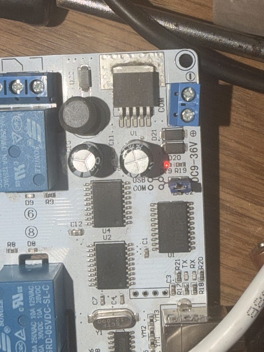
The header pinout was wrong
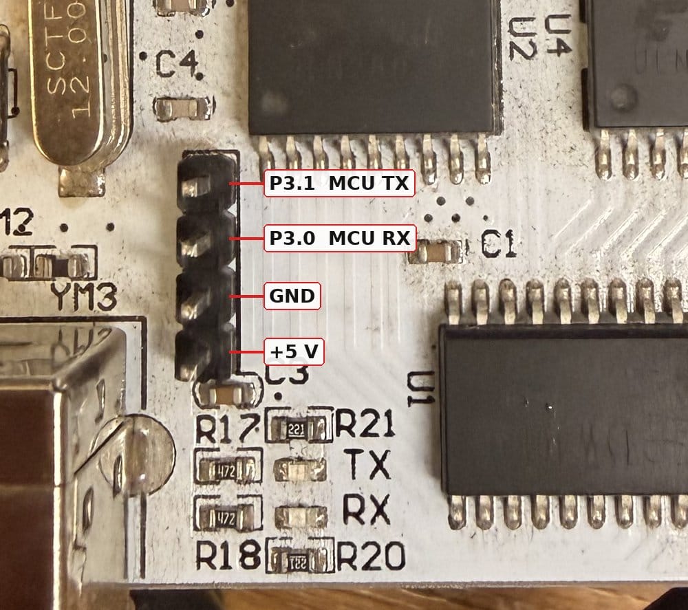
I soldered in a header and wired up a USB-TTL cable using the pin order the schematic suggested. Nothing. Swapped TX and RX. Nothing useful.
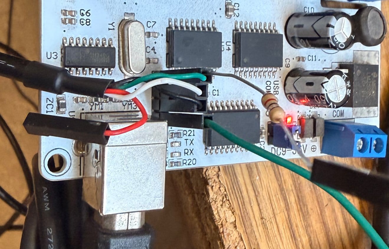
What saved me is that P3.0 and P3.1 aren't only the programming port. They also drive relays 8 and 7 through the ULN2803. So the relays became the test equipment: put the cable on, take one wire off, power it up, and see which relay misbehaves. With the black wire on the top pin, relay 7 went dead. Move it to the second pin and relay 8 went dead. A few rounds of that gave the real order, top to bottom: P3.1 (chip TX), P3.0 (chip RX), GND, 5 V. It's not what the schematic says.
Then the bootloader talked back, but in garbage, and relay 7 chattered in time with it. The ULN2803 input on P3.1 loads the bootloader's weak quasi-bidirectional output so much that its high level sags below what the adapter reads as a 1. A 1 kΩ pull-up from 5 V to P3.1 fixed it, and the handshake has worked first time ever since.
Two more traps I hit along the way:
- My PL2303 console cable has white = TX and green = RX, the opposite of the most common convention. Check yours with a loopback.
- The bootloader only runs for a moment after a cold power-up. Start the flasher, then unplug and replug the board.
Relay 2 sits on the chip's reset pin, so the reset function gets turned off when flashing. Otherwise relay 2 could never work.
A protocol in 791 bytes
I wanted a protocol you can type by hand: plain ASCII lines at 115200 baud, one command per line, and every reply is the output state the board is actually driving, not a blind echo of the command. That’s what the chip set, not a measurement of the contacts: a welded relay would still report as off.
| Command | Does | Reply |
|---|---|---|
h F0F0 |
set all 16 relays from a hex mask | F0F0 |
s 5 / c 5 |
relay 5 on / off | the new state |
r |
read | the state |
t 1000 |
failsafe: all off after 1000 ms of silence | 1000 |
i 3 |
board ID | 3 |
w |
save settings to EEPROM (only with all relays off) | the state |
v |
version | relay16 1L id 3 |
The hex mask is the same one usb-relay has always used: 0001 is relay 1, 8000 is relay 16. h F0F0 does what set F0F0 did, so the show logic carries over unchanged.
I wrote that same feature set in C first, and it came out at 1384 bytes, too big for a 1 KB chip. So the version that runs on the stock chip is hand-written 8051 assembly: 791 bytes, with room to spare. It ran in a simulator (ucsim) against a 17-test suite before it ever touched a board, and the first flash worked: all commands, the relay walk 1-16 in order, failsafe timing, and the saved ID surviving a power cycle.
The C version still exists as the “full” build, about 2.2 KB. It adds board-timed pulses (p 3 250 fires relay 3 for 250 ms and the board turns it off) and a per-relay maximum on-time, so a valve closes on time even if the host crashes in the middle of a burst. It needs the 4 KB or 8 KB chip in the same family, which drops into the same footprint, and it hasn't run on real hardware yet.
On par with the old HID boards
Same host, same day, every update checked against the board's reply:
| Stock firmware | relay16 | |
|---|---|---|
| Change one relay | ~40 ms | 3-4 ms |
| Change all 16 relays | ~640 ms (16 commands) | ~3.25 ms (one command) |
| Reply | an echo of the command | the output state it set |
1000 random 16-relay patterns, flat out: 277 updates per second, median 3.25 ms, worst 7 ms, every reply correct.
Then the race. I had the old HID board on the bench too, so we ran them back to back on the same 1000 random patterns, each update confirmed before the next:
| Total | Rate | Median | Worst | |
|---|---|---|---|---|
| Old SainSmart HID board | 3.00 s | 333/s | 3.00 ms | 4.00 ms |
| Reflashed serial board | 3.52 s | 284/s | 3.25 ms | 7.00 ms |
Old Sainsmart HID vs New Sainsmart Serial with new Firmware
Half a second apart over a thousand updates. The HID board is a hair faster and a little steadier, but both stay well inside 10 ms. I could have pushed the serial board past 115200 baud to close the gap, but on par was the goal, and about 1.1 ms of each round trip is just bytes on the wire.
At this point the firmware isn't the limit, the relays are. An SRD-05VDC relay needs up to 10 ms to pull in and 5 ms to drop out. At 277 updates a second the board sets every pattern, but the contacts can't follow and the whole bank buzzes. At 20 updates a second every pattern visibly lands.
Fast As It Can Go
20 writes a second
Fire needs more than speed
The same relay on the same board, every time. Each board stores its own ID in EEPROM. The host finds boards by that ID, whatever USB port they're on and whatever order they boot in. A missing board leaves an empty slot, and the others never slide over to fill it. Two boards with the same ID is an error, and the controller refuses to start.
Nothing left on too long. In layers:
- Relays start off at power-up. Since the bootloader runs before my code, I power-cycled a board eleven times watching for twitches. Nothing on USB power. The 9-36 V supply is next on the list.
- The board has its own failsafe. If it hears nothing from the host for the set time, it turns every relay off by itself.
- usb-relay still enforces its 2-second maximum on-time and hold times, and now sends idle boards a keepalive so the board failsafe only trips when something has really gone wrong.
I tested that last part the mean way: relays on, then freeze usb-relay with SIGSTOP for 1.2 seconds. The board turned its relays off by itself, and when usb-relay woke up it noticed and logged it.
Back into usb-relay
The last piece was teaching usb-relay to drive the new boards. It now finds relay16 boards on its own and places each one by its stored ID: by default board ID 3 is the third group of four hex digits in the mask. The show software, the MIDI bridge and the web UI don't change at all. They still send set <hex>.
It sends the new state to every board before reading any replies, so the boards work in parallel. Setting the old HID board and a reflashed board together takes 3.75 ms, about the same as one board alone. If a board drops off USB, usb-relay picks it up again by its ID when it comes back, and sets it all off.
What's left
To be clear about where this stands: it’s proven on the bench, not yet in the field. Eleven cold starts on USB power showed no relay activity, but power-up on the 9–36 V supply the rigs actually use hasn’t been checked yet, and nothing has switched a real load. That comes before any of these boards goes near propane.
The checklist:
- Power-up check on the 9-36 V supply, and a run with real loads on the contacts.
- IDs and labels for the 13 to 15 boards across Fire Kethedral, Medusa and Flower Tower.
- Running the full build on a 4 KB chip.
Try it
Everything is on GitHub under MIT: lowerpower/sainsmart-relay16.
- Hardware and flashing: the verified header pinout, the photos and the pull-up.
- Protocol
- Performance: every number in this post, and how to reproduce it.
- Board IDs and board order
- usb-relay: the controller, which now drives both kinds of board.
You'll need a USB-TTL adapter, a 4-pin header, a 1 kΩ resistor and stcgal. And remember: the stock firmware can't be read back, so once you flash, there's no going back to SainSmart's.
The old boards had a good run. With this firmware, SainSmart's new boards can finally be the replacement.